

OMG-GYRO-M5

OMG-GYRO-M5
Sensitivity gain function
1.Adjust the gain value by transmitter’s sensitivity channel, range from -100% ~ 0 ~ + 100%.
a. 0 is no gain at all.
b. -100%/+ 100% is the maximum sensitivity gain.
2. When the gain wire is not used, use the gyroscope's own potentiometer to adjust the gain value.
Instruction of Function Switch
1. EPA (Travel setting)
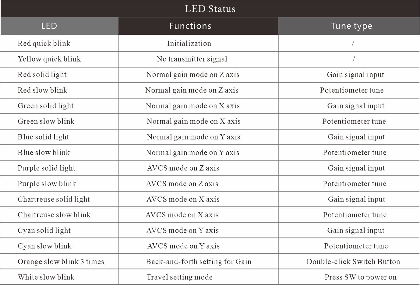
Press the “ SW ” switch to power on. White LED blinks slowly, entering to the servo travel setting . Rotate the transmitter‘s steering wheel to make servo stop at the
desired position (turn left / turn right). Short press “SW” switch, then white LED blinks 2 times quickly; red & green LED becomes solid; and blue LED blinks slowly. It
means current travel has been saved. Then rotate the transmitter’s steering wheel to make the servo stop at the other desired position. Short press the switch, then
white LED blinks 2 times quickly, and keep solid light after that. It means current travel has been saved as well. 2seconds later, the gyro will automatically enter into
initialization mode . Once the initialization is completed, gyro is ready for use.
2.Reset ( Travel Restore Default Setting)
Press the “ SW ” switch to power on and enter into the travel setting mode. After pressing and holding the switch for 3 seconds, the red LED and chartreuse LED starts
to blink alternately. 2 seconds later, restore to default setting. Then it will enter into initialization mode. Once the initialization is completed, the gyro is ready for use.
3.Back-and-forth setting for Gain
After double-click SW button 2 times under the normal working status , the orange LED will slowly blinks 3 times. Then switch-over the Back-and-forth direction of the gain.
4.AVCS mode
Press the SW switch for 2 seconds under the working status, and release the switch after the yellow LED blinks 2 times. Switch-over normal mode and AVCS mode.
5.X/Y/Z axis setting
Press and hold the SW switch for 5 seconds under normal working status, and the yellow LED blinks 3 times (Please do not release the SW switch when the yellow LED blinks
2 times at 2 seconds). Then release the SW switch and enter into the axis setting mode.
Under this mode, press the SW switch and the red LED quickly blinks 2 times and keep solid light. It is the default Z axis. Repress the SW switch and switch-over to X axis.
The green LED will quickly blinks 2 times and keep solid light . Repress the SW switch and switch-over to Y axis. The blue LED will keep solid light. If repress the SW
switch, will switch-over to Z axis again (cycling as this way).If you do not press the SW switch after entering into the axis setting mode, the gyro will exit the setting
mode and be back to normal working mode after the white LED blinks 2 times.The setting sequence of the 3 axis: Z(default)-X-Y-Z...
Note: If you do not release the SW switch after entering the axis setting mode, the gyro will keep in the axis setting mode until you release the SW switch and the gyro will exit
the setting mode and be back to normal working mode after the white LED blinks 2times.
Input Signal Type
1.If the input period of the analog servo signal is within 10-20MS, the output period of the gyroscope follows the input period.
2.Suitable for FUTABA SBUS2 signal input and servo 3MS period output.
3.Suitable for FUTABA SR signal input and SR output.
4.Suitable for SANWA SSR \ SUR \ SHR signal input and SSR\SUR\SHR output.
Contact Us Building 18, Kangcheng Siji Palm Garden, Zhongkai High-tech Zone, Huizhou City, Guangdong, 516003 China 086+13392860198 sales@rcomg.net Emergency Calls:086+157 6832 8163 | Sales Representative Coco: +86-157 6832 8163 Kelly: +86-150 8933 8975 Brina: +86-157 5747 6884 Angela : +86-158 8855 3957 Summer : +86-132 2485 7206 Flora: +86-188 4031 8667 Vickey: +86-134 8068 6896 Catherine: +86-181 6898 6905 | 
|